
 |
By Maureen Albertson |

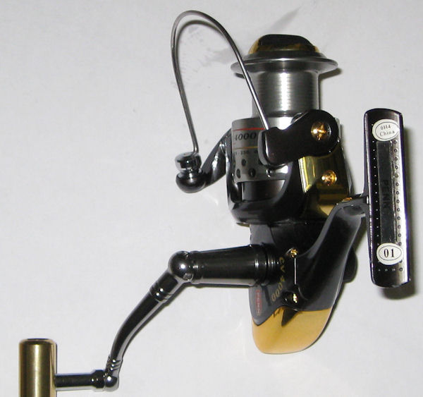
We are doing a breakdown of the CV4000 and CV5000 as a sample to help with re-assembly of these reels. Most of the images are from the CV5000.
- Quick jump to specific parts:
Or just start reading from here for the walk-thru:
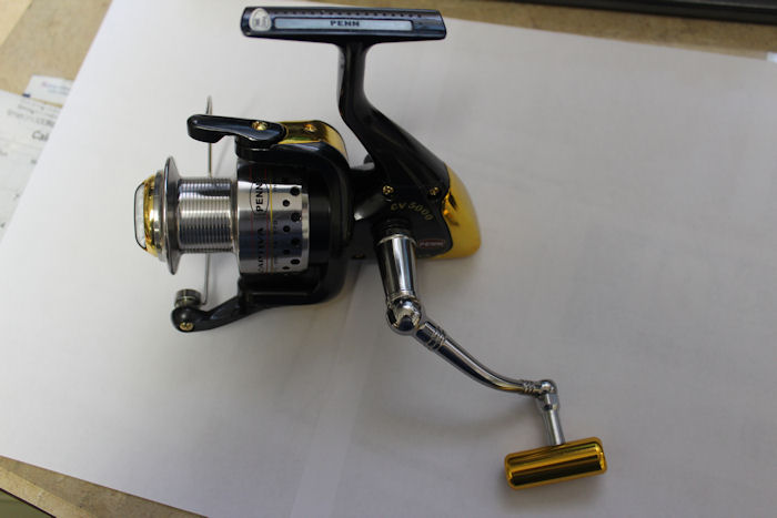
CV5000 reel break down.
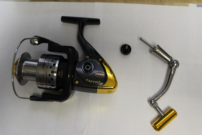
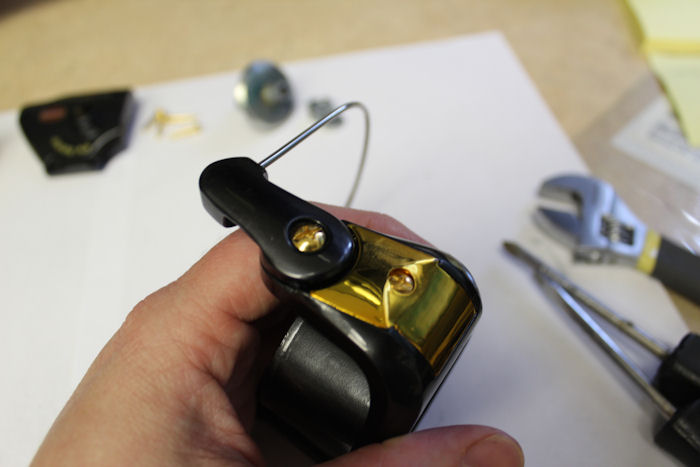
Remove the handle
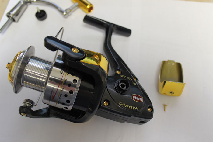
Remove the rear cover and screw.
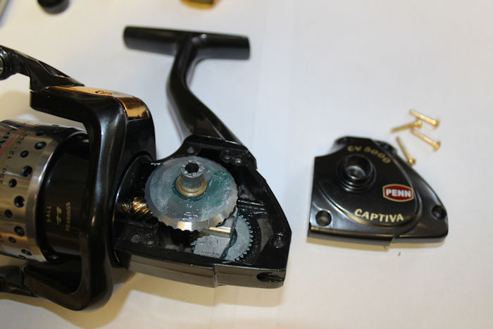
Remove the housing cover and screws.
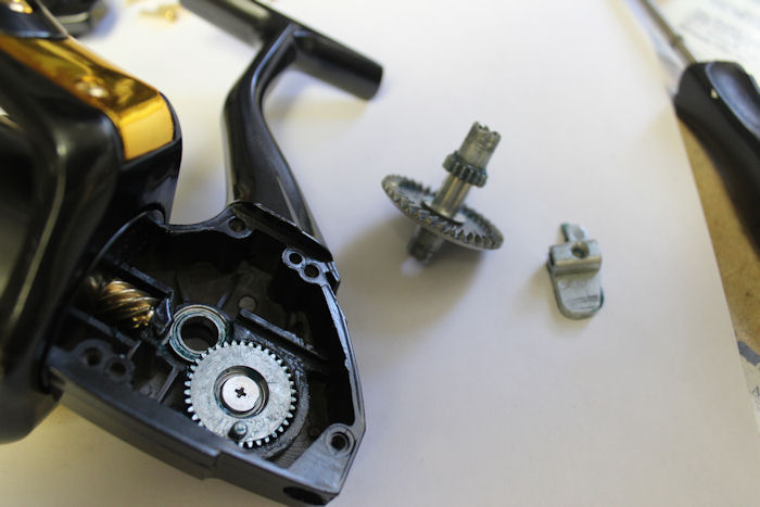
Gears and Shaft
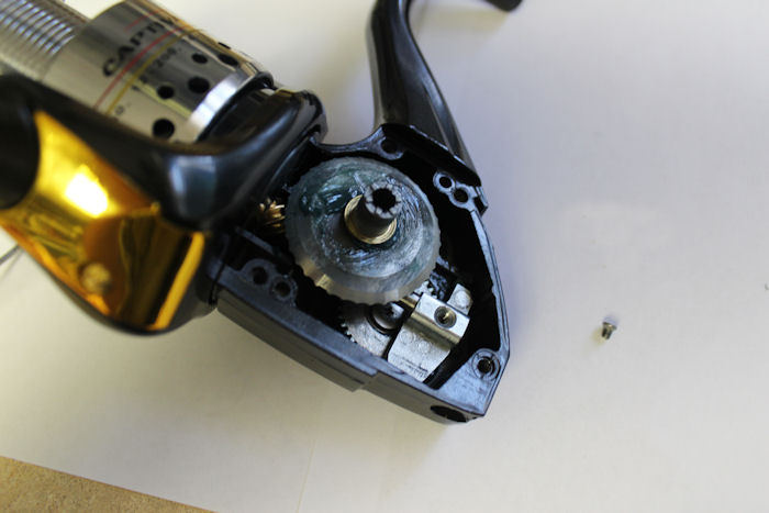
NOTE: You can see the amount of grease that Penn recommends using here in the housing. All the gears are just barely coated. None of the other parts in the front of the housing are greased at all. We don't recommend "packing" reels with grease - it can actually interfere with the movement of the gears and is unnecessary.
Remove the crosswind block screw to allow shaft removal.
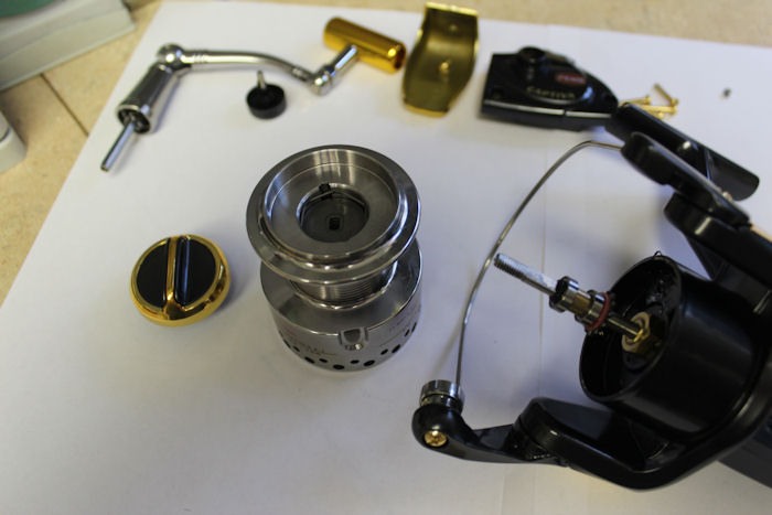
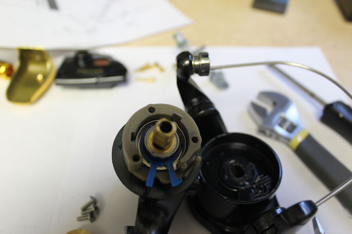
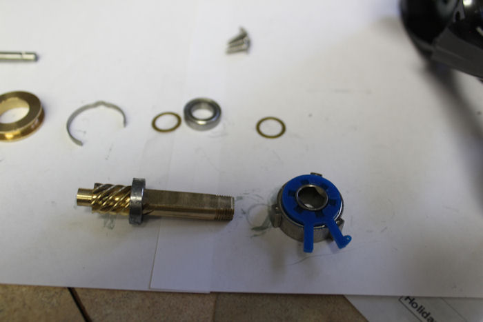
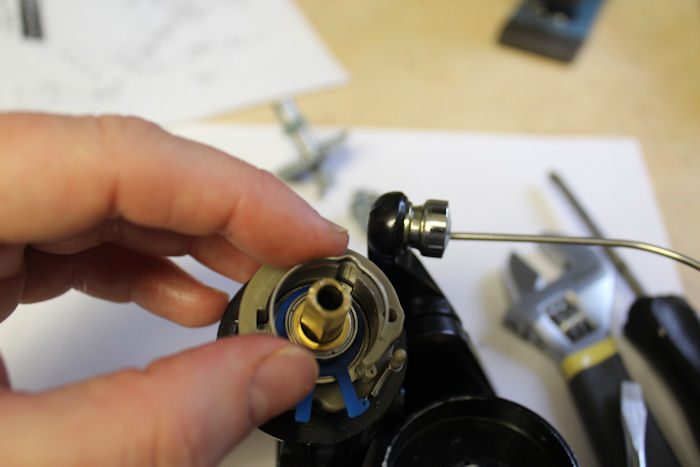
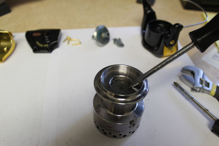
Remove the drag knob and spool. Note the position of the parts on the top of the shaft.
First, there is the o'ring, then bearing, bushing, bearing, thrust washer. On this individual reel, the assembly line put in two thrust washers, the schematic only shows one.
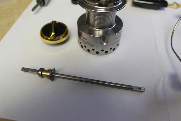
Slide out the shaft.
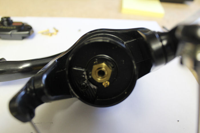
Rotor nut and locking screw are now accessible.
Remove the main gear and crosswind block at this point, otherwise they fall out anyway while working on the front of the housing. If necessary, you can also unscrew the crosswind gear and access the bearing on the other side of the housing.
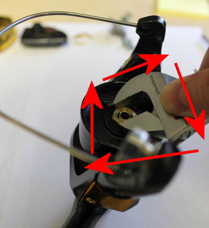
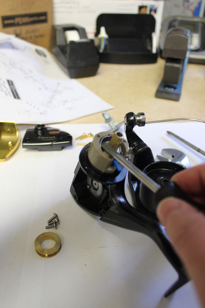
Remove the rotor nut. NOTE!!!! The threading is REVERSED on all the original CV reels, so turn RIGHT to loosen the nut!!!
Clutch Assembly
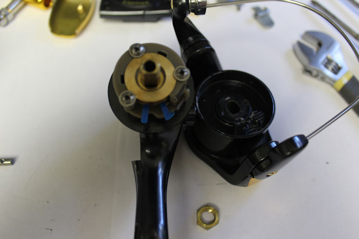
With the rotor removed, you can see the placement of the spring on the clutch and housing post.
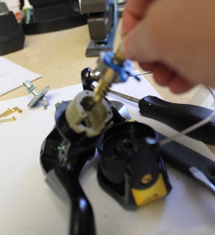
Remove the screws that hold the collar in place so that it can be removed.
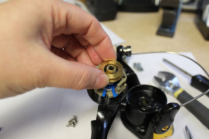
This allows you to see the positioning of the parts underneath the collar.
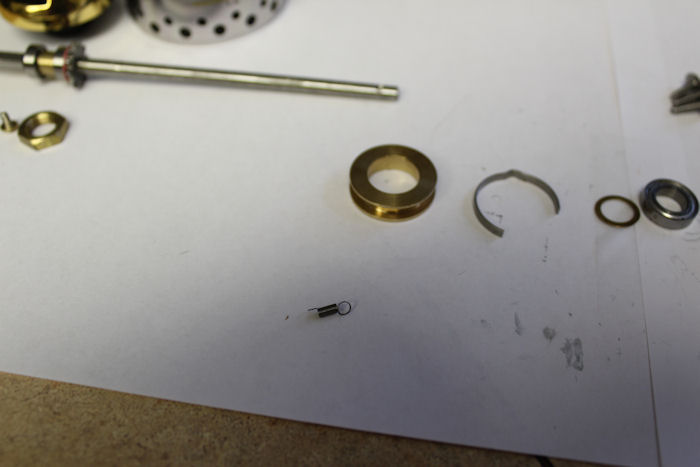
Do not loose this spring! It wasn't on the original schematics up to Rev. 4, so there isn't a part number for it that we can find. NOT REPLACEABLE. We've added it to our copy of the schematic drawing and labeled it as key #21B.
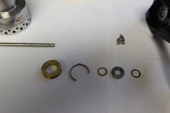
Collar and the parts below it in the order that I removed them. Collar, spring, shim, bearing, shim.
Grab the pinion and slide it and the rest of the parts out. This is the pinion, the clutch bearing assembly and a bearing.
NOTE: The clutch bearing assembly can come apart, but is only sold as a unit, so if any parts are damaged or lost, order the assembly as shown here.
The assembly is very lightly greased. Flat edge of the inside race of the clutch lines up with the flat edge of the pinion gear when reassembling.
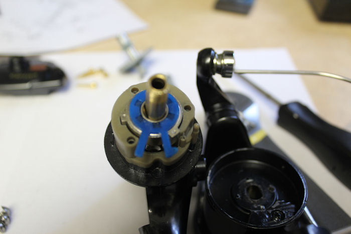
When sliding the pinion, bearing and clutch back into place, line up the square blocks on the clutch with the notches on the housing and seat all the way down.
To put the clutch bearing spring back into place, the smaller, open end of the spring hooks into the small hole on the wider blue arm on the clutch. The larger ring hooks over the post on the housing.
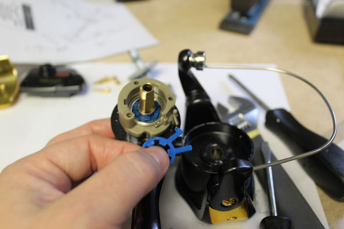
I found that it was easiest to remove the part of the clutch with the arms, install the spring and hook the loop over the post FIRST, then slip the piece back onto the top of the clutch and snug it into place.
Put the spring back in, lining the crest up in the notch on the housing as shown.
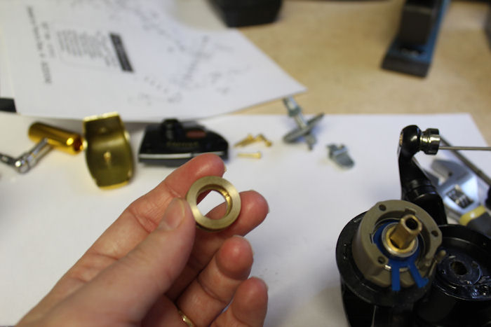
The collar has a top and a bottom. The bottom has a nested area for the bearing, so that the bearing is partly inside the collar.
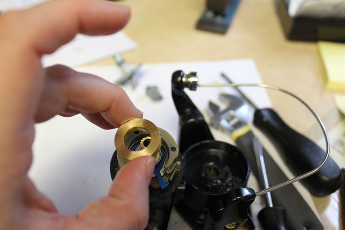
The top of the collar is solid. Seat it over the bearing, snugged down so that it stands flush to the edge of the housing, then put the screws back in place to secure it.
Putting the rotor back on the housing. Line up the end of metal (28-4000CV trip lever) so that it sits in between the two arms of the clutch.
REMINDER! Reversed threading on the nut, it's LEFT to tighten.
Bail Spring Installation
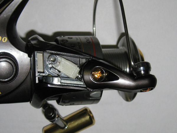
Start by removing the key#22 screw and #27A plate, to expose the bail spring assembly.
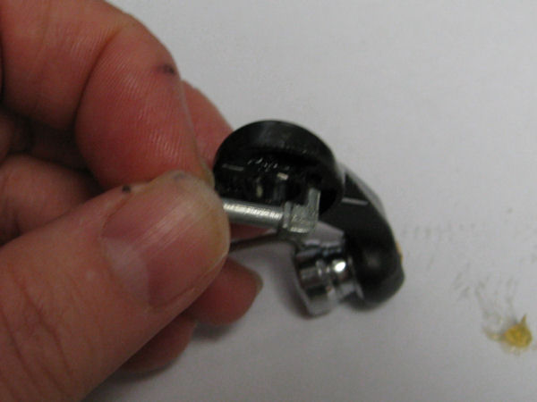
Remove the #31 screw from the bail arm, and gently lift the bail arm as you push the white #34B pivot guide further onto the bail spring, allowing the whole assembly to gently come off the post in the rotor that holds it in place. You can see the short end of the #28 trip lever sticking up just below the spring in this photo.
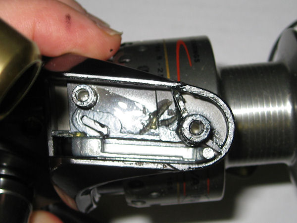
This shot shows the #28 trip lever seated down in the rotor correctly, with short end sticking up. NOTE: Part #28-4000CV and 28-4000CLL are absolutely identical and either one can be used.
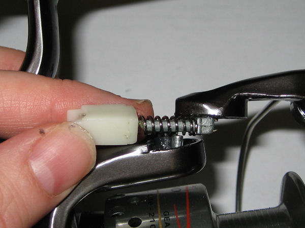
Putting it back together. The short end of the #34A pivot arm goes into the hole in the bail arm.
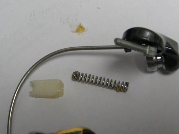
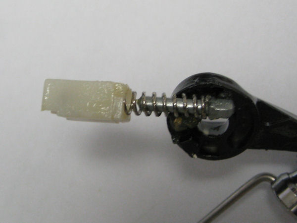
Then you put the long #32 bail spring onto the long end of the pivot arm, followed by the #34B pivot guide, curved end to the pivot guide pointing out.
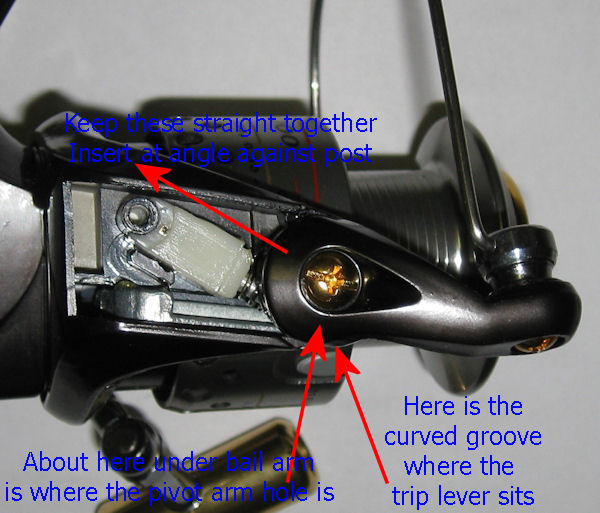
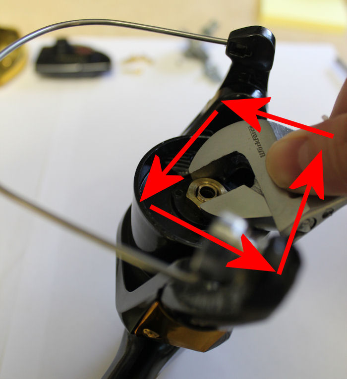
Now back to one of my earlier photos, with added notes. When putting this back together, you have to apply steady pressure, and the guide/spring/pivot assembly must be evenly aligned, or you can end up bending the spring and then the arm will not seat correctly.
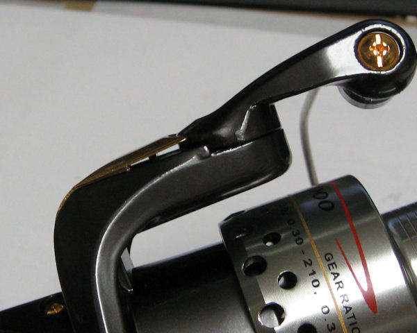
It can be tricky to keep everything positioned correctly while you try to seat the bail arm onto the end of the trip lever. If you see this gap, it's likely something isn't seated all the way down. NOTE: the curved end of the pivot guide has a cut side, this should be facing up as shown in the photo.
AND STILL: with everything correctly in position, the bail is tempermental and doesn't always want to flip. IT WILL DO THIS ON REELS RIGHT OUT OF THE BOX. If it is opened at the point shown in the photograph, it won't flip over. You end up having to manually turn the rotor until it flips.
This may be why Penn decided to discontinue the series? We aren't sure, but it's a likely culprit that may have led to the CV2 series.
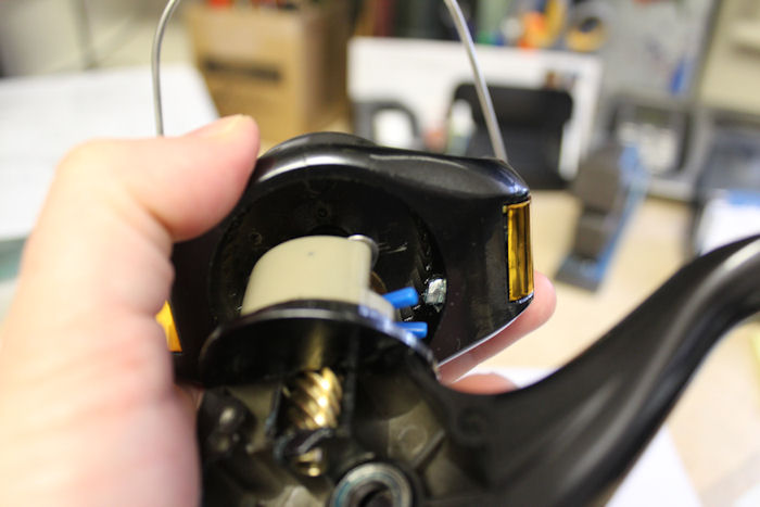
The cover on the side opposite of the line roller is purely decoration on the CV500, CV2000, CV4000 and CV5000, CV6000 reels, there is nothing under it. On the CV8000, this is reversed: The bail spring and trip lever are on the side opposite the line roller and the line roller side cover is empty underneath.
Drag Washers
Pop out the spring that holds the drag washers in place. Hang onto it with your other hand as you do so, so that it doesn't go flying!
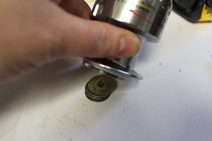
Turn over and tap to drop out the stack.
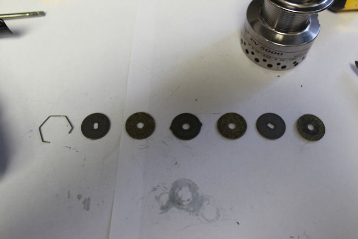
This is the order of the drags from the spring to the bottom of the stack. Yes, those washers are FELT.
Clicker
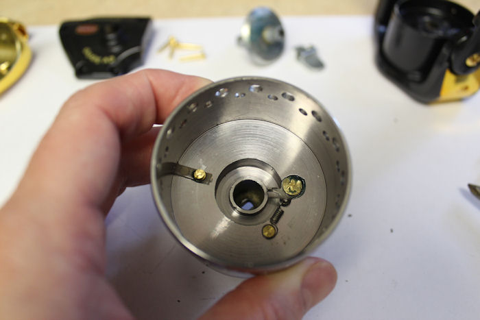
Proper positioning of the clicker parts underneath the spool.
Order parts online for this reel(s):
https://www.mysticparts.com/PennParts/Spinning.aspx#CaptivaFamily


2 Comments