
 |
By Maureen Albertson |

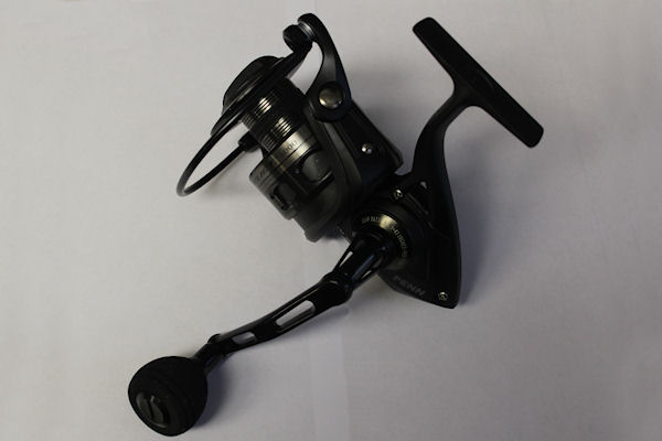
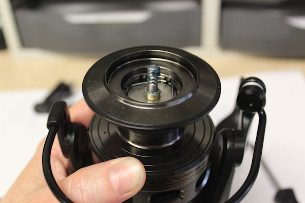
A sample breakdown of the CFT6000 Conquer to help with re-assembly of these reels.
- Quick jump to specific parts:
- Bail Spring
- Cam and Trip Levers
- Clicker
- Clutch (Anti-Reverse)
- Crosswind
- Dog and Dog Spring
- Drag Washers
- Gears, Main Gear and Crosswind Gear
- Gear, Pinion
- Line Roller Assembly
Or just start reading from here:
Breaking Down The Reel
I'm only using the key #s from the drawing. For full part numbers, see page 2 of our schematic: CFT6000 Schematic
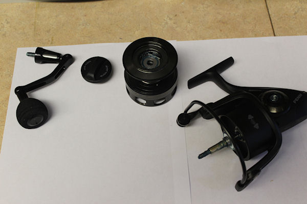
Remove the #15 handle, #52 drag knob and #47 spool. You'll see #60 thrust washer on the spool shaft, be careful not to mis-place it, as it also might stick on the underside of the spool.
Main Gear and Crosswind Gears
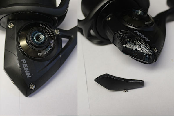
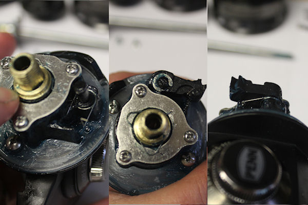
IMPORTANT! #226A and #226 rear cover must be removed FIRST, if you want to remove #45 housing cover to access the gears and crosswind block assembly. Penn has the underside of the housing under the #226 cover greased, probably for extra insulation against water.
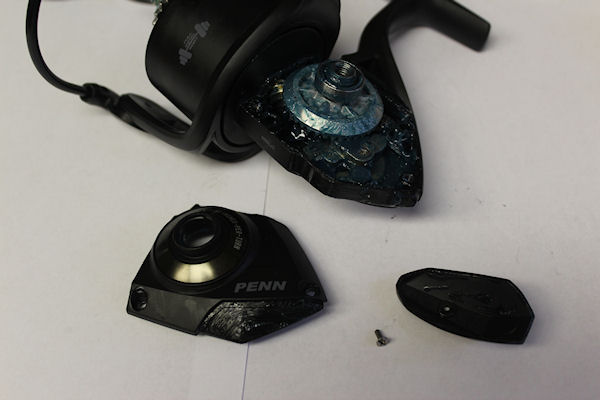
NOTE: The smoke grey rings on the #45 housing plate and #1 housing of the reel are part of those items and cannot be ordered separately, so do not try to remove them.
Crosswind
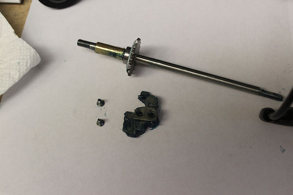
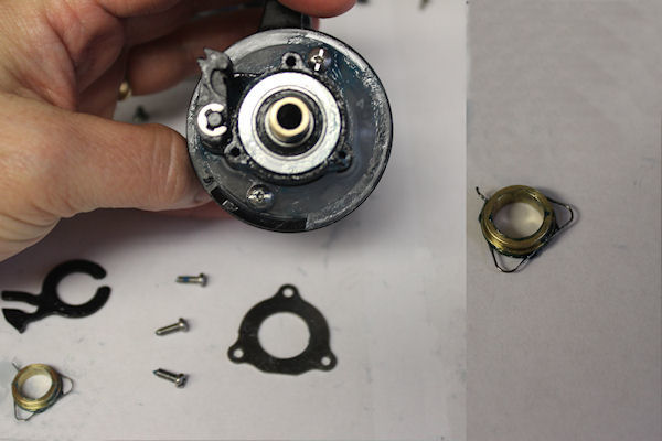
Unscrew the two #44 screws to slide out the #39 spool shaft and remove the #43 crosswind block. If you need to check or change the bearing on the spool shaft, pop the #40 c-clip (bearing lock spring) off with a slim screw driver. Use needlenose pliers to put the clip back on.
Remove the bearings to check them for roughness. On the short shaft of the #8 main gear, the #8 shim goes on the shaft between the main gear and the #20 housing cover bearing. If you need to check the #20 housing bearing, remove the #231 crosswind gear from the housing.
There is a flat tip on the upper part of the #43 crosswind block, that sits underneath the #43A crosswind block plate in the upper part of the housing. The block then rides along the plate as the #231 crosswind turns. When reassembling, make sure that the block is set properly on the peg on the crosswind gear and is straight with the flat tip under the plate.
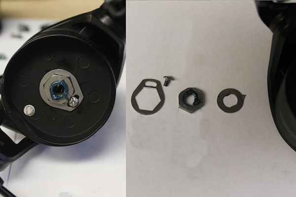
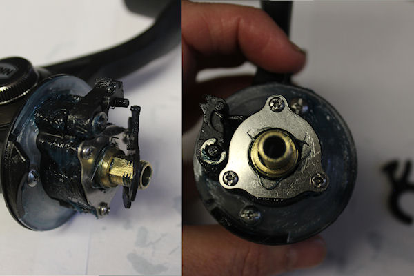
The #38 rotor nut is snug but not overtightened, held in place by the #95B locking plate and #38A screw.
Clutch (Anti-Reverse)
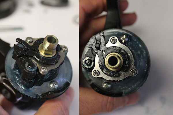
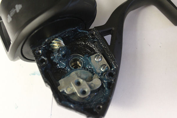
Note the positioning of the #10 A/R Holder (Anti-Reverse) against the #4 dog.
Under the #10 is the #12 A/R busing spring wrapped around the #11 bushing. The hooked end of the #12 goes up into the hole in the #10 A/R holder that is just below the Y shaped arm of the holder.
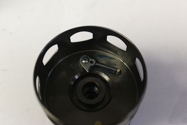
Dog and Dog Spring
The #5 dog spring sits on the post on the housing as shown here. The long hook end goes up and into the curved cut in the #4 dog that sits on top of the spring. If you need to change or reinstall the spring, use a slim screw driver to pop off the #6 clip and needlenose pliers to slide it back on afterwards. If you have a repeated problem with the spring exploding, try cutting the spring but remove NO MORE THAN 2 rings from it. Too much, and you'll kill the spring.
Gear, Pinion
If you need to access the #19 pinion gear, #20 upper/lower pinion bearins or the #98 clutch, remove the #21 bearing cover plate. For the purposes of this walk thru, I did not remove these items.
Cam and Trip Levers
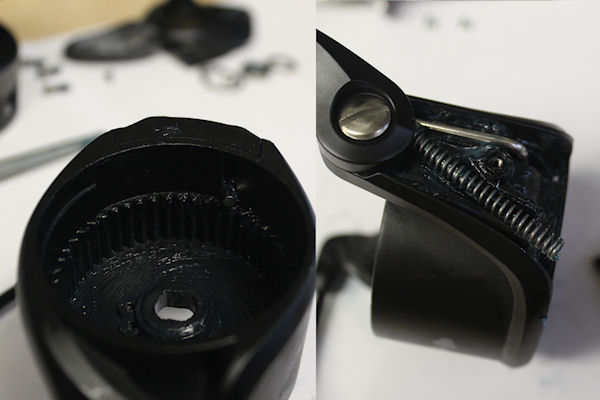
Underside of the #27 rotor, where you can see the one leg fo the #28 trip lever protruding. When you remove the #27A cover do so carefully, as the bail spring will explode outward when it is released from the cover.
Bail Spring
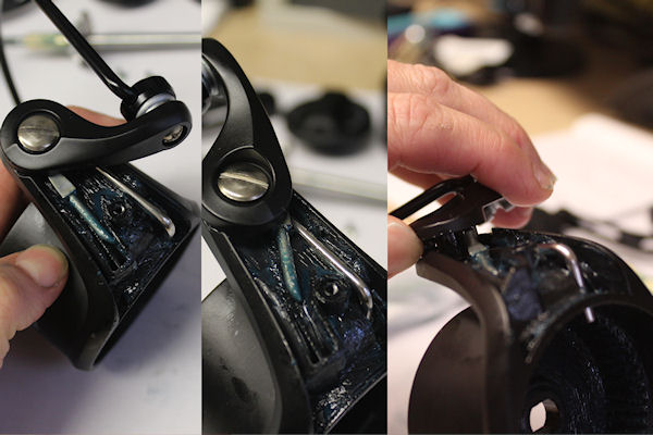
Bail in the open position showing the #34C pivot arm. To install the bail spring, make sure that the bail wire is in the closed postion. The bent leg of the #34C sticks up into the grove of the #34 bail arm as shown.
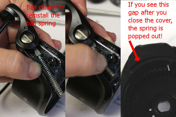
Installing the spring. Put #32 bail spring onto the #34C pivot arm, with the bail wire in the closed position. There is a lot of tension in this style spring, so it will fight you. Hold the spring with your thumb once you have the end tucked in, and slide the #27A cover back into position to screw it down. NOTE: If you see this gap, the spring is NOT in position and you will need to reinstall it again.
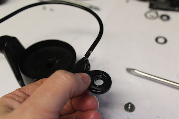
Line Roller Assembly
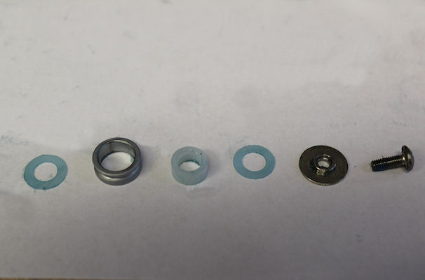
The order of the line roller pieces are as shown.
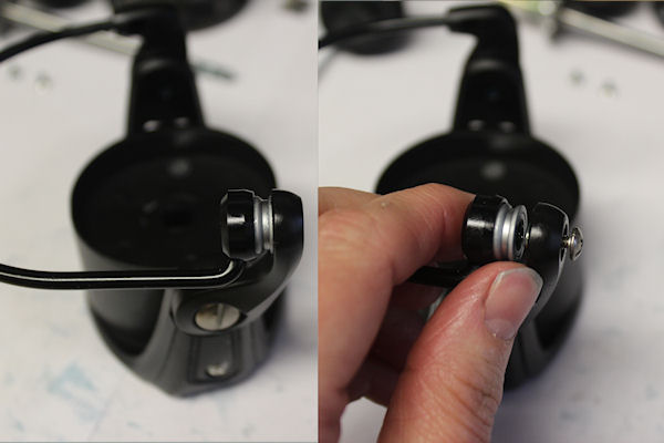
The fatter end of the line roller sits toward the bail wire. When reinstalling the pieces, it is easiest to put the first 132A washer, #35 roller and #35A bushing onto the wire side first. Then tuck the other #132A washer and #132 metal roller washer into the #34 arm. Then push everything together and lock into place with the #36 screw.
This #25 paddle end comes as part of the #24 bail wire, but on this model it does have it's own part number so that it can be replaced by itself if needed. Put on in this direction then turn clockwise to lock it onto the wire, then screw it onto the #27 rotor with the #31 screw.
Clicker
View of the clicker assembly.
Drag Washers
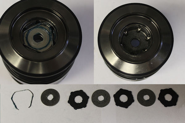
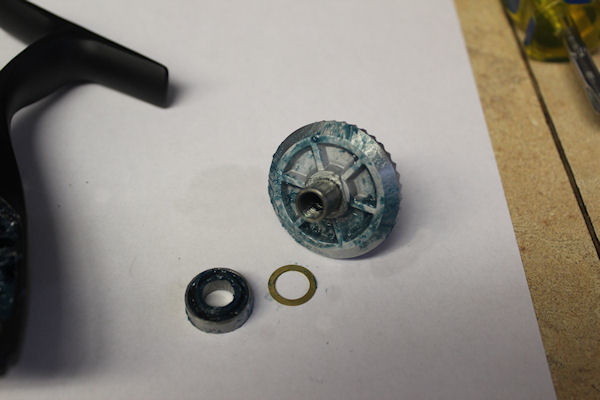
Spool top before and after removing the drag washer stack. The order of the washers is as shown. Install the washers from right to left, with the HT100 washer going in first, then alternating with the #57 keyed washers and ending with the #51 spring on top to hold them all in place.
After reinstalling the drag washers, seat the spool back onto the shaft. Make sure that the straight edges of the keyed metal washers are lined up with each other, or the spool will not seat all the way down on the shaft.
Order parts online for this reel(s):
https://www.mysticparts.com/PennParts/Spinning.aspx#Conflict
0 Comments